W6SI Blog Page (Entry 8)
4/11/2017
V/UHF Dual Band J-Pole Antenna
For very small number of readers, I am sorry, it’s been a long time I’ve written anything for this blog.
It is not for the lack of subject to write on. It is purely due to my laziness (and non-radio related activities that has been occupying great deal of my time for the past 1++ year). But here now, I am back, and hope to be a bit more active in the future.
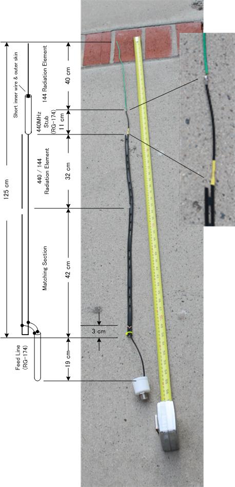
DBJ-1 J-Pole Antenna
(before housed in PVC tubing)
Back in June 2015, I think, I wrote about an odd-ball J-Pole antenna I was using for 2m and 440 at the base station here. It had an odd arrangement for two separate matching section for 2m and 440, which did not seem so theoretically sound. It worked anyway, but for a low power transmission, even just a piece of wire would do, so you never know.
Since then N3GO OM, out of the blue, made a constructive discussion and sent me a good set of diagrams and software utilities, related to J-Pole design. If interested, you might download the piece from his web site: N3GO's Radio Workshop.
Before I started doing this J-Pole study, I never figure out what this antenna is, and how it operates. In fact, no one I talked to on the subject knew how this everyone-knows antenna actually operates. Now after a bit of research, I think I know better. J-Pole is a ½ wave vertical dipole with matching stub section at the bottom. ½ wave antenna has current distribution further up from feed point (the bottom, that is), and should have a lower radiation angle compared popular ¼ wave GP variety. There is no stated gain per se, but I consider it a preferred base station antenna. And if you build this type of antenna for HF band, it would work better for DX than ¼ wave vertical. But more on this in the future discussion.
As I stated earlier, the “matching section” for the J-Pole is a stub matching, necessarily tailored to a single band. So dual band J-Pole arrangement is a bit tricky, and thus the strange dual stub arrangement of my old copper pipe antenna. Since then I found a good technique to overcome that problem. In fact, the built version of the antenna is available, for cheap.
He solved that problem by inserting a coax “trap” in the strategic position of the radiation element. It is strategic, because it cuts off the top portion of the element for 440MHz radiation, and the bottom section length is such that its stub matching feed point is just right for both bands.Because the trap also works as a loading inductance for 2m, the overall length of the antenna is slightly shorter than full size J-Pole, which is ½ wave length plus matching section, or about 1.5 meter; this one is about 1.25 meter. Note the picture of the installed antenna. Notice the lack of radials for the bottom section. It is a quite low profile antenna.
The interested reader (a good standing ARRL member) should download the old article from ARRL web site. In the article, he publishes measured data comparing this DBJ-1 J-pole to VHF ¼ wave mobile antenna, a rubber duck antenna, and a “standard VHF J-Pole”. DBJ-1 matched the performance of the reference mobil antenna, and better than all other types. I take his word for it, as I do not have a facility to test it myself like that.
As I mentioned, you can buy a finished version of the antenna from e-Bay. It sells for about $30, and you add a section of PVC pipe to make it a respectable outdoor antenna (becauswe the cost of a PVC pipe is far less than the shipping if he has to send it to you). It is constructed of 300ohm twin lead, and the coax section is made of thin RG-174 cable. I like building something like this, but considering it takes some “doing” to attach the thin coax to twin lead, I opted to buy one from him, instead. The design is patented, but Dr. Fong generously permits all amateurs to build one for yourself, though he appreciates buying one from him.
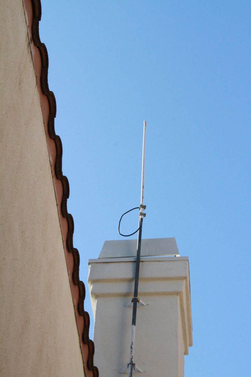
DBJ-1 is mounted on my chimney
To house this antenna in a rigid casing (for structural strength and weathertisation), Dr. Fong suggests to use Schedule-200 PVC pipe, which is a bit thinner skinned than normal schedule-500 pipes. I found mine at Loew’s.
As far as I could tell, all PVC pipes I found at Home Depot were Schedule-500.
Of course, if you couldn't find the thinner walled variety, it's not the end of the world. The antenna should still work, and mechanically a bit stronger.
Caution: thicker PVC wall tends to shift resonant frequency of the antenna downward. You may have to cut some length of the antenna in such case.
As it came, the antenna was resonated somewhat lower (145.00MHz) than I would have liked, but has bandwidth wide enough, that I did not care to cut the element to adjust. The antenna is raised September last year (that’s 2016), on my chimney and it’s up there working since. It is not grounded like the previous copper element J-Pole. No problem seen.
I will discuss a little more about this grounding issue, but for now, I state it almost doesn't matter if you do so or not. In a practical sense. There is a theoretical reason to ground it, but in practice, in most installations, it does not make much of a difference. BUT!!! It is HIGHLY recommended that your feed line (coax, that is) have an RF choke,. a.k.a. Unun at the feed point. a few rounds of coax loop should do. This is because the way it is, J-Pole has absolutely no protection agains common mode current flowing through outer conductor of the cable, which never is a good thing.
Oh, and I neglected to mention: In the latest March 2017 issue of QST, he showed adding the 220MHz coverage to this antenna. Another curious idea. A recommended reading.
[Disclaimer: I have no business relationship with Dr. Fong, I just respect him and like his antenna. I will not gain financially if you buy the antenna from him. This is my personal recommendation, but not a business endorsement.]
Above is a reflection of my thought and only mine. But if you have any questions, feedback and/or suggestions, please send me an e-mail. I might reply on this page (sorry, no guarantee)
| Home Page | Blog Index | Next Blog Entry |