W6SI Blog Page (Entry 10)
5/23/2017
Impedance Transformer for Multi-Band Antenna
In the last installment, I talked about a non-resonating vertical antenna that operates on most any HF band with an impedance matching coupler. The idea isn’t new, but I wanted something that operates nearly ½ wave length on 20 meter band, and not so long as 43 feet so 15 meter and above can still work reasonably.
This means that for most of the band, except for 40 meter, is fed high impedance. And those electronic antenna coupler does not work well at extreme load impedances. They may not tune to something that high / low, and if it does, it can arc or burn, even if you stay within the “spec-ed” power limit). One of the reason for the mysterious 43 feet length for the popular non-resonating verticals are that at that length, most ham bands are in a moderate impedance range at feed point. So what to do?
An impedance transformer, otherwise known as 1:n balun / unun. As you know, balun is a coupling network between balanced (such as dipole antenna) and unbalanced transmission lines (such as coax cable) , whereas unun is a coupling between unbalanced and unbalanced lines. In this case, I want unun with 9:1 impedance step-up.
Why 9:1? A voltage feed (i.e., high impedance) antenna such as this end-fed monopole, have feed point impedance of a few Kohms. Since our feed line is 50 ohm, 9:1 bring it up to ~450 ohm, so within SWR of 2 to 3 range. Antenna couplers can deal with that.
9:1 unun is available from good people like Palomar Engineers and DX Engineering. But what’s the fun in just buying those, when you can build one yourself. I happened to have a few 2.5” diameter ferrite toroid in my inventory, so I decided to wind my own.
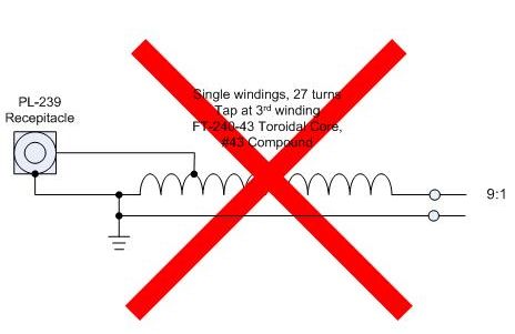
Figure 1 Single wound Auto-transformer
<* Big Failure Warning: Do Not Try this at Home*>
My initial plan was a single-wound auto-transformer, like figure 1. Simple and easy thing first. I used a PVC jacket-ed 14 Ga wire on 2.5” toroid (FT240-43, the biggest toroid I had in inventory), and the most I can wind is about 30 turns. The 9:1 tap is about 3 turns. Ah, no. It didn’t work.
This is because the input link does not have enough windings to produce sufficient inductance. You are just feeding the input power to ground, heating up the wire in the process.
So out the way was this simple monofalar transformer idea.
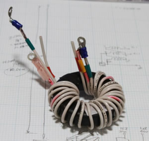
Got to do it the right way. If you want a 4:1 balun (or unun), you need to do bifilar windings, i.e, two independent wires wound together side by side. For 9:1, you do tri-falar, or three wires wound side by side. This is not difficult, but takes some getting used to, especially if you would like to use a wires of decent gauges to allow fair amount of power to go through. I used PVC insulated 14 gauge .
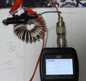
Look at the figure 3 for how the trifalar toroid looks like. How do I know this is working? I hooked up a 300ohm resistor to the load side of the unun, and measured the impedance from input side (Figure 4).
 Figure 4 Impedance testing |
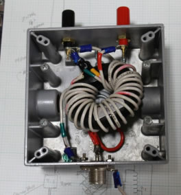
 Figure 5 Housed in a utility box |
Any antenna analyzer with impedance reader can be used. I happened to use MFJ -226 VNA (the cheapest VNA you can buy today). It reads 36.9 ohms at 9MHz. The impedance increases as frequency goes higher (to about 100MHz), and that’s mainly because the resistor is not a non-inductive RF variety. The toroid itself looks good enough for the HF application.
So I housed the finished unun to an exterior utility box I bought at a local hardware store (Figure 5), a.k.a. Denault's True Value. It is reasonably weather tight and cheap. The moisture will get inside no matter what, so I drilled a hole at the bottom so water can get out. I’ve had this thing out there during wet winter this year, and it stayed dry and working.
Now I have a working 9:1 unun. Don't know yet if / how I would use it for my Mission Viejo Special Mark2 project (it's been hooked up in the antenna still work in progress), but it was fun doing it.
(to be continued…)
Above is a reflection of my thought and only mine. But if you have any questions, feedback and/or suggestions, please send me an e-mail. I might reply on this page (sorry, no guarantee)
| Home Page | Blog Index | Next Blog Entry |


